Power Generation utilities have extremely varied needs, and that’s especially true for filtration. Plant priorities will vary widely from base load or peakers, new or almost retired plants, costal or desert locations. Technology has evolved greatly in the last 40 years, moving from Roll-O-Matic pad filtration to Efficiency Particulate Air Filter (EPA). While EPA filtration for gas turbines is nothing new, it is becoming more common with many power plant gas turbine operators.
As gas turbine technology evolved, new alloys have permitted higher firing temperatures and smaller tolerances on profile parts, increasing turbine efficiency but at the cost of increased sensitivity, raising the importance of maintaining blade integrity. With higher efficiency and reliability requirements, operators and turbine manufacturers slowly realized that the air entering the turbine needed to be as pristine as possible to maintain top performance. With better tools for performance monitoring, operators are now better equipped to make a cost/benefit analysis than ever before.
Camfil has been an integral part of this filtration evolution supplying EPA filters to the gas turbine industry offshore since 1986, then to coastal power plants where salts and/or hydrocarbons where problematic. It is now becoming a standard on most new baseload installations.
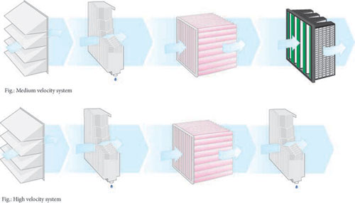
In offshore filtration, reducing salt penetration was seen as the key to reducing corrosion while increasing engine availability and reducing maintenance stops. Reducing salt penetration has traditionally been tackled either by reducing water penetration or by considering salt as a particle and increasing system efficiency. Focus on reducing the seawater intake led to the typical high velocity vane system designed around coalescing filters and weather vanes. High velocity systems had a key first fit cost advantage due to their smaller footprint. Meanwhile, Camfil has typically been promoting a filtration system based on total system particle efficiency. Specialized testing has shown that removing only water droplets does not guarantee salt particle efficiency, as there are still salt particles in the air. EPA product developments were thus driven by total life cycle cost considerations instead of capital alone by including the total impact on turbine running conditions. Typical considerations include power output reduction due to fouling or pressure drop increases, cost of filter changes, cost of unavailability, maintenance cost, etc.
Life cycle cost considerations for the operator
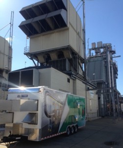
When looking at an individual filter, efficiency as rated according to ASREA/ISO standards is just a small part of the picture. Efficiency is a laboratory measurement done under dry controlled conditions. Power plants are not located in laboratories; actual site conditions and particle types vary widely. These conditions are better replicated through specialized gas turbine test rigs where relative humidity can be added or even better, directly on site under real-world conditions using tools such as mobile laboratories or isokinetic probes located upstream and downstream of the filter stages.
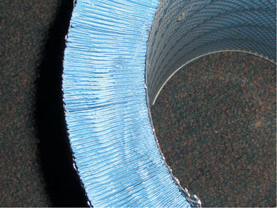
On site testing has shown that ensuring efficiency under humid conditions was more challenging than under dry conditions, highlighting the importance of water tightness in a filter to prevent any by-pass. Factors influencing water tightness includes the design around the sealing of the media pack within the filter, and, on static filters, how many sides are glued. The latest generation of filters has been moving towards double sealing design where there are multiple applications of glue. Drainage is also critical for water tightness, and features such as vertical pleating and water drains in the frame help by avoiding any water accumulation. If drainage is not achieved quickly enough, the accumulated water will build pressure drop to a point where water will be forced through the media no matter what its efficiency is. It is also important when looking at vertical pleats to ensure that the glue beads are open enough not to reduce the drainage effectiveness.
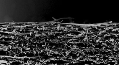
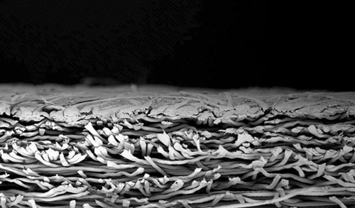
Pulse filters are particularly sensitive to pressure drop spikes caused by humidity. The type of media is a key factor to consider. The industry has moved away from cellulose/blended media towards synthetic designs as they offer stronger fibers and typically maintain their strength better when wet. More recently, specialized products utilizing 3-dimensional media have been released to handle humid conditions. They react better than two-dimensional surface loading medias as they avoid issues such as dust cake swelling. Two-dimensional medias are typically surface loading and they rely on the formation of the dust cake. Dust cake swelling happens when hygroscopic particles in the surface dust cake absorbs ambient moisture from the air, increasing their size and restricting air flow, causing high pressure drop spikes.
Total filter pressure drop is the combination of restriction of airflow from the media and from the shape or construction of the filter. Only increasing media efficiency without optimizing the rest of the filter construction will impact the pressure drop negatively and raise the life cycle cost. Other general filter aerodynamics and configuration have an impact on reducing pressure drop, such as grid design, extended depth on static filters, pleating shape or optimization of media area for each filter grade. Optimizing media area is not equivalent to maximizing media area. There is a point where adding additional filter media has a negative impact. When the media is pleated so tightly that it is not open to airflow, part of the media is not being used during the life of the filter, adding unnecessary cost and pressure drop.
Another benefit of onsite testing is evaluating the cleaning ability of pulse filters. Many people associate dust holding capacity with filter life, but measuring dust loading capacity in a laboratory test is misleading as it compares dust loading capacity in static mode with standardized particles size. Real-world filter life is dependent on the cleaning ability of the filter, something not measured by standardized testing. Optimizing for dust holding capacity may then lead to counterproductive steps such as increasing filter media area, but at the cost of reducing overall filter life by restricting the ability of the filter to pulse clean – the characteristic that provides the majority of filter life.
Differencing between EN779 and EN1822
EPA definition has evolved over time. Originally HEPA meant 99.97% efficiency on 0.3 m particles but the current EN1822:2009 standard is based on efficiency on the most penetrating particle size (MPPS), usually between 0.08 and 0.15 m. It is important to understand the order of magnitude in efficiency that this represents over lower grade filters. For example, F9 grade filters rated per EN779:2012 measure efficiency at 0.4 m. A typical barrier filter such as the CamGT F9 meets the required 70% initial efficiency at 0.4 microns, while a typical E10 grade filter rated per EN1822:2012 offers 98% efficiency at 0.4 microns – reducing particles penetration by a factor of 15:1.
When specifying which level of filtration, one should always refer to the latest standard. For example, EN779:2012 includes a minimal efficiency requirement that was absent from the 2002 version, which only rated filters based on the average efficiency of the filter – a combination of the low initial efficiency and the higher efficiency over the life of the filter that would typical increase as the filter is loaded with dust. Independent test reports helps ensure minimum requirements are met, but it is only one part of the picture. It is important to remember the effects of other factors such as water tightness filter construction, pulse filter cleaning ability, media types, etc.
If higher is usually better, why not U15 filters on a gas turbine?
It all comes down to life cycle cost consideration. Typically with an E10 final filter, operators will wash once a year. An E12 filter offers over 99.5% efficiency and will keep the compressor clean, eliminating the need for washing. Upgrading further to U15 would raise efficiency to 99.9995% but with no incremental operational advantages. It would also add pressure drop and filter cost. The filter house themselves are not built to guarantee U15 filtration, and significant costs would be added to reach this efficiency level. For example, in clean room or pharma applications, where such filters are usually used, gel is used on all seams of the room to guarantee airtightness.
Considering the complete system
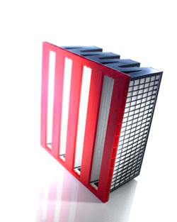
When looking at gas turbine EPA filtration, it is important to consider the whole system, the environment and usage of the turbine. On multiple stage barrier systems, the pre-filter(s) choice becomes important, as it adds to the total efficiency, can help coalesce water to reduce re-entrainment of particles, and prolong the life of the final filter. Filtration is always about protecting what’s behind the filter, even if it is another filter.
Before upgrading an existing installation, it is important to also consider the integrity of the filter house and transition after the final filter. If there is corrosion or by-pass, it will be worth repairing. A minor grid upgrade might be required to ensure proper sealing. The size of the filter house will also affect the efficiency by changing the air velocity through the filter media.
To make an informed decision before buying or retrofitting an inlet filter house, users may consider asking for the following:
- Site evaluation: to look at the current inlet system requirements with the potential of upgrading for better filtration needs.
- Life cycle cost calculation: to determine optimal filters for your operation and environment.
- Site contaminant air sampling test: to confirm the level of efficiency that is required.
- On-site testing with a mobile lab: if there are recurring issues, to confirm the optimal system or to distinguish between manufacturer’s claims.
