The earliest use of activated carbon for gas-phase contaminant removal dates to 1854, when a Scottish chemist invented the first mask that utilized activated carbon to remove noxious gases. Wood was originally used as the base material for gas masks since it was good at capturing poisonous gases when converted to activated carbon. By 1918, it was determined that shells and nuts converted to activated carbon performed even better than wood.
Around this same time, activated carbon began to be produced on a large scale and its use spread to decolorization in the chemical and food industries. In the later 1900s, other industries, such as corn and sugar refining, gas adsorption, alcoholic beverage production and waste-water treatment plants, began to use activated carbon.
Today, activated carbon is available in many different shapes and sizes and its applications are growing every day. For air filtration, the most common types of activated carbon are granular activated carbon (GAC), pelletized activated carbon (PAC), and structured activated carbon.
In addition, other substrates such as alumina and zeolite are used in lieu of activated carbon due to their tremendous pore structures. With this diversity of adsorptive substrates, the term “chemical media”
is often used to capture all products that remove gas-phase contaminants from the air.
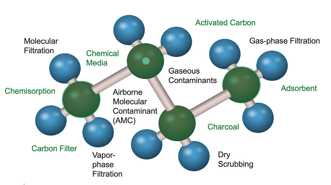
While being a molecular representation of the volatile organic compound (VOC) toluene, Figure 1 also contains various terms that are associated with molecular filtration.
Gas-Phase Contaminants
Gas-phase contaminants are undesirable airborne molecules that are mixed with the normal molecular oxygen and nitrogen found in the air we breathe. Because of their molecular size in the sub-nano range, they are not visible. Also not visible, but present in the air, is desirable molecular water, which is referred to as humidity. Some common, undesirable gas-phase contaminants are hydrogen sulfide (the rotten egg smell), skatole (dirty diaper smell), VOCs (chemical and food odors), and ammonia. Many gases that evolve from combustion are contaminants, such as carbon monoxide, oxides of nitrogen, oxides of sulfur, and polyaromatic hydrocarbons.
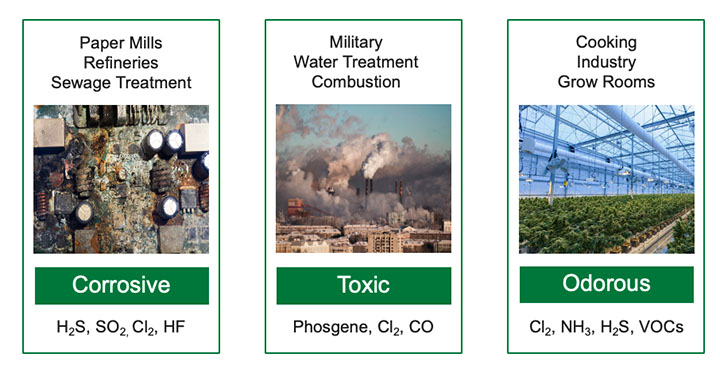
Corrosion control, odor control, and protection from toxic gases are the three main categories of molecular filtration. Figure 2 shows these categories along with some typical applications and additional contaminants.
Note that there are often gas-phase contaminants that span more than one category. Most of the time, contaminants span two categories. A good example of this is hydrogen sulfide (H2S) which is both odorous and corrosive.
Particulate and Gas-Phase Contaminants
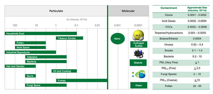
The graphic in Figure 3 illustrates the relative size differences of airborne contaminants.
Some particulate contaminants, such as viruses and bacteria, although not visible, have a mass size large enough to be filtered with specialized particulate filters. Gas-phase contaminants can only be effectively removed using molecular filtration technologies.
Control of Gas-Phase Contaminants
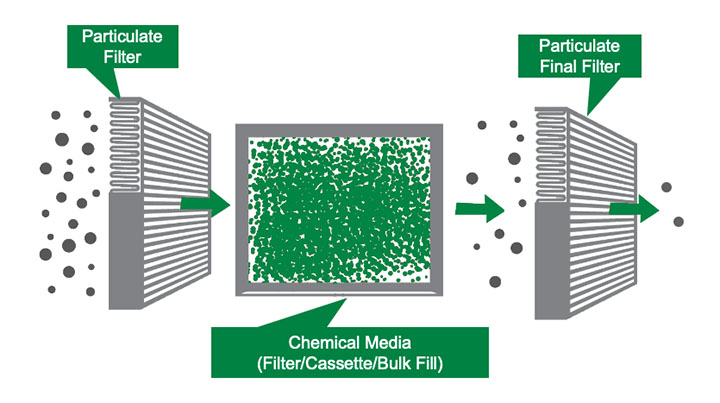
There are various ways to control gas-phase contaminants. One method is source control, wherein the source of the contaminants are relocated or eliminated. This rarely works since most contaminants are generated by the application in question. A second technique is ventilation, where large amounts of fresh air are added to the contaminated air to dilute the contaminants. This typically isn’t desirable due to the large amount of energy required to heat or cool the fresh air. In addition, ventilation doesn’t remove the contaminants from the air. That leaves the tried-and-true process of molecular filtration systems. A schematic of a molecular filtration system is shown in Figure 4.
Molecular filtration devices are used in combination with particulate filters to remove gas-phase contaminants. A particulate filter is always required upstream of the molecular filter to ensure that all dirt and dust is removed from the airstream. This is critical to ensure that the vast pore structure of the chemical media is left unabated for the adsorption of gas-phase contaminants. A particulate final filter is recommended downstream of the gas-phase filter when the air is going to be recirculated back into a space occupied by people or critical processes. The purpose of this particulate filter is to capture any dust that might come off the chemical media in the molecular filter. When the air is exhausted to the atmosphere, there is generally not a need for a final filter.
Selecting Molecular Filtration Devices
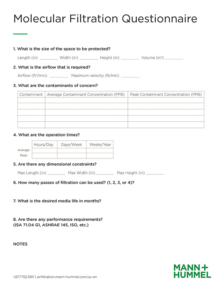
Choosing the correct chemical media type and the correct chemical media delivery device is a daunting task. There is a lot of information that must be gathered first, such as the contaminants of concern (COC), the concentrations of the COC, the air volume, the desired chemical media life, the space available, and more. A good starting point is completing an application questionnaire like Figure 5 to document as much of this information as possible.
The gathering of the data is the first step in determining the correct chemical media type. In most applications, there is one chemical media type that will work best. There are times, however, when more than one media type will work or when more than one media type is required. Two or more different types of chemical media may be needed if the list of contaminants that needs to be removed contains multiple contaminant families.
To further complicate matters, there are multiple chemical media delivery devices that are available and most of the time, more than one of those devices will work. The amount of space that is available along with number of media types required are the two main factors that will determine which delivery device will best solve the application at hand. Due to this complexity, it is recommended that you reach out to your local filtration specialist to assist you with making the proper selection.
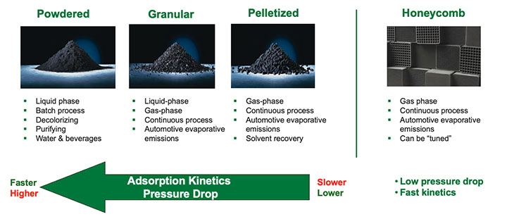
The chemical media that is utilized in molecular filtration devices is available in many forms. Figure 6 provides an overview of these forms.
There are times, however, when more than one media type will work or when more than one media type is required. Two or more different types of chemical media may be needed if the list of contaminants that needs to be removed contains multiple contaminant families.
Powdered versions of chemical media are less commonly utilized for gas-phase filtration due to the high pressure drop associated with them. Granular and pelletized chemical media are the most prevalent types in the market, and structure media like honeycombs are gaining traction due to their fast kinetics and low pressure drop.
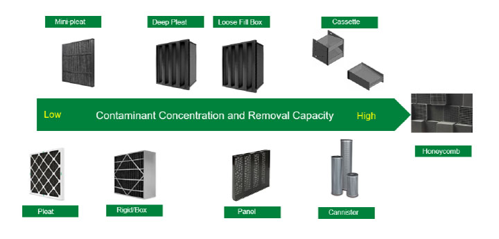
Figure 7 shows typical molecular filtration devices that are widely available. The products shown are displayed from left to right by their relative contaminant removal capacity. For any given application, there can be more than one molecular filtration device that will work.
The Minimum Viable Product
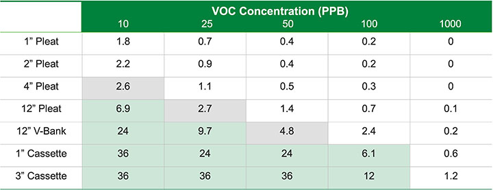
The minimum viable product is usually determined by the customer or end user and is defined as the minimum acceptable service life of the molecular filtration device before the chemical media removal capacity is exhausted. Figure 5 demonstrates how there is usually more than one viable product solution for most gas-phase applications.
As an example, Figure 8 shows the expected life in months versus the contaminant challenge for various molecular filtration devices. The gray boxes show acceptable products for roughly a three-month minimum life and the green boxes show acceptable products for a six-month minimum life.
When evaluating a gas-phase application, it is important to understand the most important requirements for that application, such as first cost, replacement cost, ease of replacement, and space available so the best product value is chosen.
Mass Transfer Zone
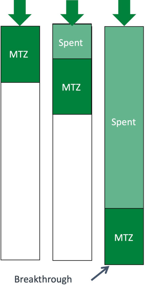
Another important point when looking at molecular filtration applications is the mass transfer zone (MTZ). The MTZ is the section in a chemical media bed where there is active adsorption. The length of the MTZ is highly dependent on media type, gas concentration and flow rate. The MTZ remains the same length and moves as the upstream chemical media becomes consumed. Breakthrough occurs when the MTZ reaches the end of the media bed as shown in Figure 9.
The lifetime of a molecular filtration device should be calculated taking the MTZ into account. Note that the values in Figure 8 do not consider the MTZ. If they did, the values would be smaller. This is because the length of the mass transfer zone with higher concentrations would be longer than the depth of the chemical media bed. This would create an immediate breakthrough of the contaminant.
Remaining Life Analysis
When the best chemical media has been determined and the filtration device has been selected, the question of how long this filtration device will last often comes up. The manufacturer of the filtration device should be able to provide an estimate of the expected life of the chemical media. To verify that estimate, the remaining life of the chemical media can be tested. Remaining life analysis compares the known, initial capacity to the current capacity of chemical filtration media that is installed in filtration systems. The information obtained from this testing can be used to confirm system performance, determine the media replacement schedule, and to assist with inventory control of replacement media. Replacing media based on testing maximizes the media life, reducing the total cost of system ownership.


