It is widely accepted that gas turbines (GT) require an inlet filtration system to protect them from contaminants contained within the vast quantities of air they consume. Having the correct system in place will protect GT performance, help maintain power output levels, increase reliability and availability, reduce maintenance overheads, and help prevent unscheduled shutdowns. Inlet filters are employed to meet all the challenges presented by a GT installation, in the harshest of environments.
Choosing the right filter media is important – but irrelevant if the air and moisture can bypass it
Filters contain pleated media and are designed to maximize filtration area. Any damage to these pleats, however, can create a bypass route for air and moisture. To ensure strength through the entirety of the pleats, including the edges, inlet filters should be reinforced in several ways. Components and designs that allow the flow of compounds evenly through the pleat channels ensures encapsulation of the pleat tips, reducing bypass opportunities. In addition, edge seal technology, which applies a continuous application of hydrophobic hot-melt beads at the border of the pleat pack creates a secondary reinforcement seal.
As seen in Figure 1, the effect of standard filter sealing in wet environments can significantly increase the risk of moisture by-pass and result in corrosive contaminants reaching the turbine. However, it is not just the sealing of the media that will affect performance. As seen in Figure 1, the impact of pleat spacing, height and depth on pressure loss (Dp) and dust holding capacity (DHC) will impact the effectiveness and utilization of the media. Optimization of the media enables maximum effectiveness.
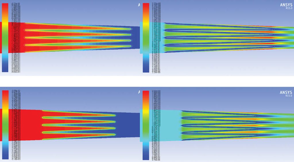
CFD modelling and other tools can be used to show the impact of pleat spacing, height and depth on Dp and DHC on any given media and its efficiency. It delivers specific information that enables the effectiveness and utilization of the media to be optimized for all environmental challenges. Modelling through the proprietary media optimizer helps improve performance for the best of the best outcomes for all filtration variables.
How many environmental factors cause galvanized steel to rust?
One of the first problems filters can succumb to is rust. It is an age-old problem but one that is rarely addressed. Where relative humidity is above 60%, salt is nearby (so any location near the sea) or the environment is wet, galvanized steel is prone to corrosion. Other hazards causing corrosion include acids such as hydrogen sulfide, which may come from natural gas or sewer gas, sulfur dioxide pollution from diesel exhaust fumes in urban areas, and even volcanoes or springs. Strong alkalis, plasters and cements from nearby industry that contain chlorides and sulfates, acid rainwater and cooling tower drift all create an environment for rust.
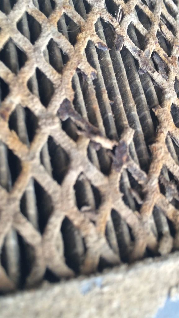
Most sites use water driven cooling towers to condense steam and recycle the water into the steam system. These cooling towers use hydrochloric and sulfuric acids and chlorine to prevent algae build up in the cooling tower. The evaporation of some of the water in the cooling tower creates clouds of mist at ground level (drift) that can be sucked into the air intake along with some of these chemicals. Furthermore, contact between galvanized items and dissimilar metals, such as aluminum, iron, or steel, also causes galvanic (electrochemical) corrosion; an electrolytic corrosion reaction between the zinc coating and dissimilar metals when in the presence of an electrolyte such as rain, dew, fog, or condensation.
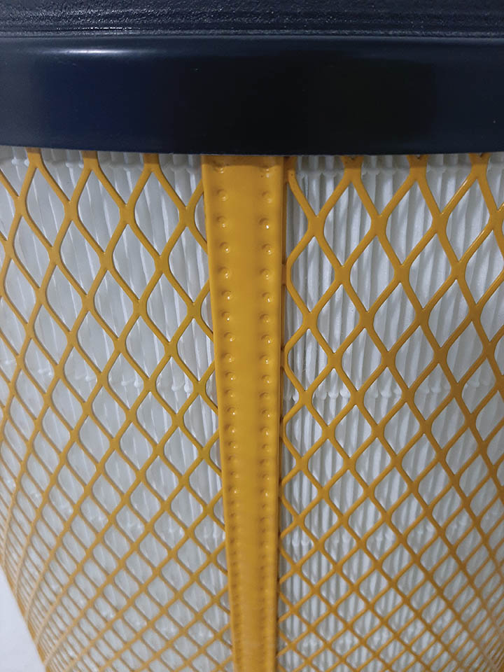
To help prevent corrosion, galvanized metal components can be powder-coated for added resistance. Resistant to cracking, peeling, chipping and abrasion, this coating helps prevent rust and damage due to chemical exposure and, as the coating features cross-linked materials that provide a waterproof finish, it also protects the metal from rust due to moisture or humidity. Over 1,000 hours of third-party lab accelerated salt spray testing shows the strength of the metal with the engineered powder coating remains virtually unchanged after this time, which is a dramatically different result from similar tests carried out with galvanized metal alone.
Real-world experience leads to cutting-edge filter design
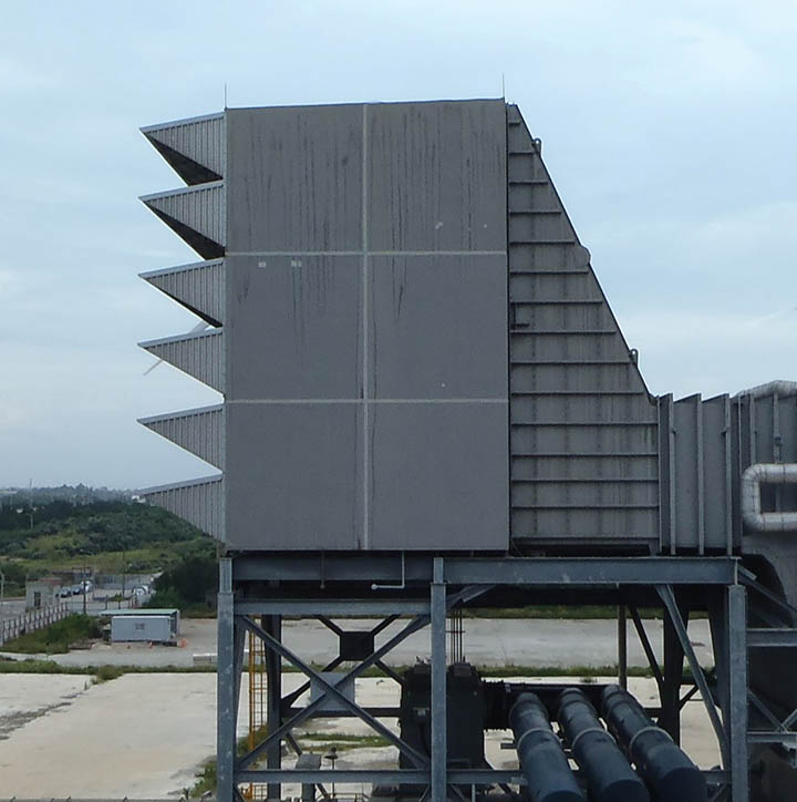
Many customers with GT sites near the coast can experience a high degree of turbine corrosion due to heavy moisture and salt aerosol. On visiting sites, air intake issues are routinely found that include poor sealing of flanges, inadequate drainage, under-performing weather protection (Figure 5) and incorrect filter sealing. All of these are major contributors to corrosive contaminant bypass into the GT. Regardless of these system wide failures, inlet filters are engineered and iterated to do as much as possible to keep salty water and particles out of the GT.
In the drive to continuously improve its products, over the years Parker has built up a world-class collection of testing capabilities and procedures in its labs to simulate extreme environments, which go way beyond any international standards available today. Continual efforts to “break” filters in these facilities and identify possible leak paths that exist or occur under any condition. When these are found, the filter design is improved to remove the possibility of this from happening in the future. As it is not possible to simulate every single environmental permutation, wherever possible secondary failsafe sealing is incorporated into the filter design as a back-up.
Parker subjects new and used filters from the field to extremes of temperature and vibration to get the different parts to expand and contract to try to get them to move around. Several wind tunnels are utilized to test under all conditions of moisture, high humidity, mist, salt fog, rain and monsoon, to subject filters to as many moisture conditions as possible.
Figure 6 shows a filter in the test rig and a leak being identified using UV fluorescent die in the water. The leak is also captured with a high-resolution camera while the rig is running. Once identified, further investigations are undertaken to identify why the filter is leaking.
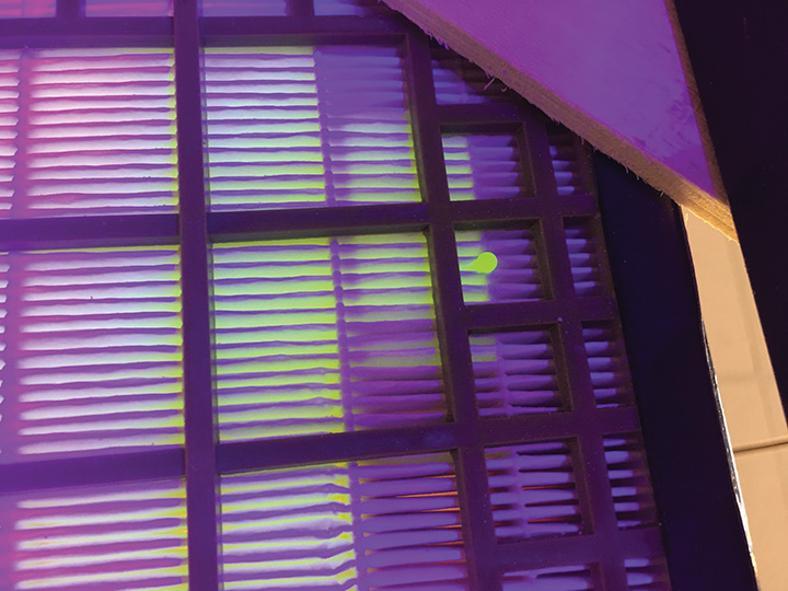
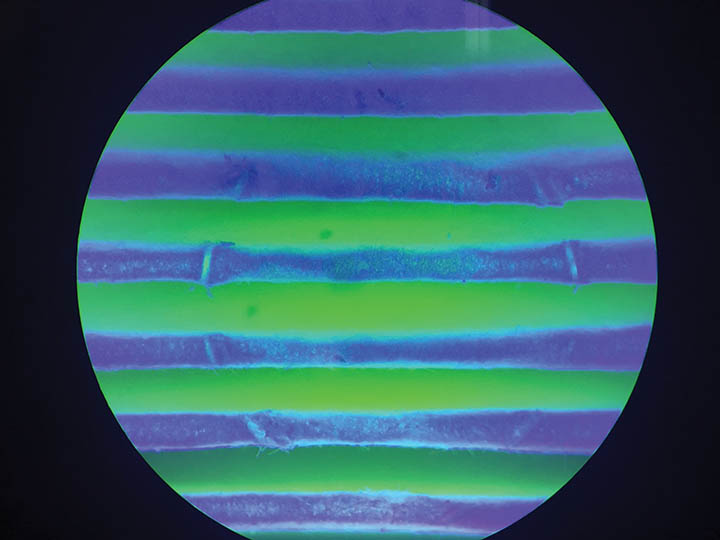
Figure 7 shows some slight damage to the media pleats within the filter from the vibration of an adjacent component, which could lead to a leak. Leak paths are identified using leading diagnostic testing methods, including CT scans, filter cut ups, the use of filters with transparent frame material to enable visualization, and dye testing.
While many sites have major contributing factors that result in bypass that are not related to the filters, it is important to use cutting-edge diagnostic technology to identify areas of product improvement and engineer solutions. It is this diagnostic testing experience, understanding of real-world problems and a desire to fully investigate why issues could arise that helps deliver the best filtration solutions in GT applications.
Parting thoughts
Great filter design is about more than just media efficiency and is dependent upon the weakest link or sub-optimized aspect in the system. All components need to withstand the harsh environments and multiple contaminants that GT systems are exposed to continuously. Because of this, every detail of a filter should be engineered based on decades of real-world experience to ensure it supports predictable, reliable, optimized GT performance.


