Manufacturing Fluids Filtration Systems
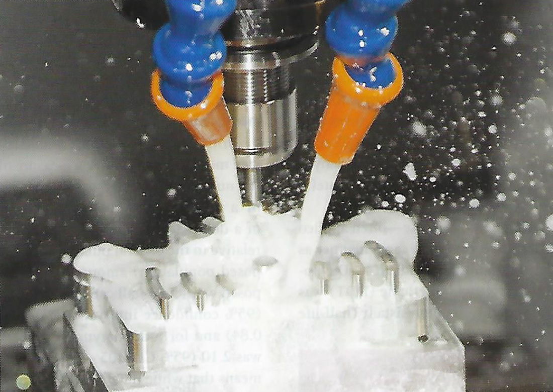
The objective of this article is to explain the various arrangements for cleaning manufacturing-process-liquids. Most industrial applications use a closed loop concept. The closed loop concept recirculates the fluid so it can be reused and the cost of replenishment can be kept at a minimum.
The main feature of manufacturing systems is that the process continually sends contaminants into the fluid as it operates. This phenomenon is somewhat different than most other types of fluid cleaning applications, where the contaminant level is reduced as the fluid cleaning function operates.
In addition to the continual addition of contaminants, the system has another major difference. The fluid is exposed to contaminants from three sources.
- Direct result – contaminants that are purposely created by the process; i.e., grinding.
- Indirect result – contaminants which are generated as a byproduct of the process; i.e., fine particulates abraded off the sheet stock during a rolling mill operation.
- Foreign – contaminants which come from the environment of the plant; i.e., plant garbage, debris, tramp fluids.
Closed loop, with its constant recirculation, is the best way to cope with these. Manufacturing fluids do not have to be totally cleaned. The fluid must be just clean enough for the process to keep operating properly at the expected quality.
Definition of Terms
Due to the evolution of manufacturing jargon, it is important to define the meaning of the different terms used in this article. Hopefully this will minimize misunderstandings of the terms. Terms such as filtration, separation and clarification have become loosely used to a point where one title is found for more than one type of cleaning device. The goal is to guide the use of these terms so they refer to a specific device.
Clarifier is the general term for equipment which cleans fluids. These include both separators and filters.
Separator are cleaning devices which use a specific physical characteristic of the particulate to remove it from a liquid which also has specific physical features and takes advantage of how the two relate to each other.
- The solids may be heavier than the liquid so separation can be accomplished with settling
- The particulate may be lighter, then flotation can be used
- Magnetic material separation can use magnetic attraction
- Centrifugal which generate a greater force on the solids for effective separation
Filter is a device which provides a barrier to intercept the solids as the fluid flows through it.
Closed Loop Systems
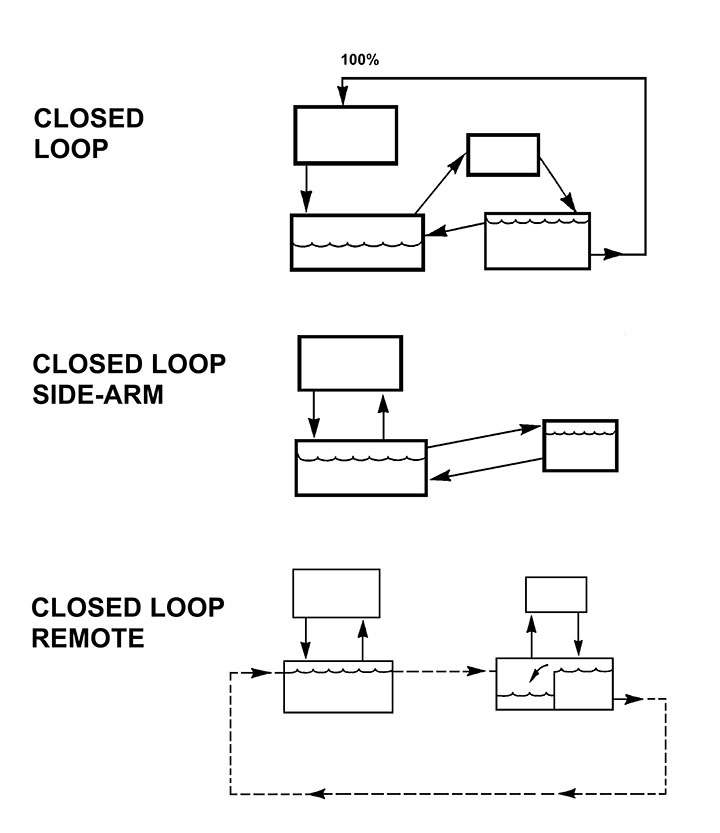
Figure 1 shows the most popular arrangements of cleaning systems. The actual arrangements for manufacturing fluids are called “closed loop.” The most used arrangement, regardless of
installation size, is the full flow closed loop arrangement. The fluid in continuously recirculated so it can be reused.

Full Flow
The arrangement is called full flow when the flow to the device equals or greater than the flow rate going to the process. It ensures that all the flow passes through the cleaning device. The flow shows where the fluid is contaminated at the process and is sent to the dirty liquid reservoir. From there it is sent to the cleaning device at a flow rate which is slightly higher than the flow rate going to the process. The extra flow returns to the dirty reservoir as a second closed loop.
There are four major components:
- Process – the actual manufacturing operation which generates contaminant as it produces the product.
- Dirty liquid reservoir – the holding chamber for the contaminated fluid. It can also be fitted with a self-cleaning conveyer to remove settled solids. When a conveyor is added, the dirty liquid reservoir becomes part of the fluid cleaning component and works in conjunction with the cleaning device.
- Cleaning device – the main cleaning function. Fluid scan consists of one or more cleaning devices. All closed loop schematics show a cleaning device in each arrangement. The device can be any apparatus as described in the paragraph on definitions. The device in the schematic may not be just a single unit. For this discussion it may include many pieces of cleaning equipment combined to intercept the varied range of contaminants.
- Clean liquid reservoir – the tank or compartment which holds cleaned liquid ready to supply the process. It always has an excess flow rate to allow some of the liquid to flow back to the dirty liquid reservoir in an independent loop.
Side Arm
This arrangement was once called “bypass” but the title is not as popular because the term is now used for other system flow situations. It is often referred to as “kidney loop.”
It uses one main reservoir where the process and cleaning device flow from and to the same tank independent of each other. The flow rate to the cleaning device can vary depending on the flow rate and clarity levels needed for the process, and the size and efficiency of the cleaning device. Also, the main reservoir can be fitted with a self-cleaning conveyor so it contributes to the fluid cleaning function. The side arm arrangement’s main value is that it can be installed when there is no room or the installation is too complex for a full flow arrangement.
Batch
A batch arrangement is used when the plan is to remove all or a portion of the volume in the main reservoir on a routine schedule and send that liquid to a remote area where another cleaning system is set up to treat the fluid. This is a remote operation and often installed when there is no room for a full flow or sidearm arrangement close to the production facility. It is also used for a recovery procedure: for the fluid or solids which may have a value. It works on the theory of volume turnover and is an effective rule.
The arrangement requires an effective procedure to transfer the fluid from the main reservoir to and from the remote unit. This usually is a piping loop or dedicated transfer tanks.
Conclusion
Any one of these arrangements can be used to reach the desired clarity levels as long as the selection of components in the arrangement meet the needs of the system, Full flow is the best arrangement and satisfies the expectations of the operator since they see that all fluid flows into the cleaning device before the liquid is sent to the clean liquid reservoir The other arrangements have their place in a facility. They do not treat all the liquid as the full flow set-up, but they can reach the desired clarity levels to satisfy the needs of the process.


