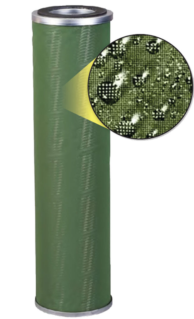
In the world of industrial filtration, one of the most common activities involves the removal or displacement of water from another liquid. However, this process is further subdivided into three distinct phases. Chronologically, the first of these phases is particulate filtration (sometimes referred to as prefiltration). This aims to remove all the particulate out of a liquid before it enters the next phase of the process. At the second stage, coalescing, the liquid moves through a coalescer where the process of creating small droplets of water that then combine into larger droplets so that it is heavier and thus easier to remove before the third phase, separation. It’s this second phase of coalescing that will be the main subject of this discussion. However, before diving too deep into the world of coalescing, it is important to have an understanding of how the other two phases affect the coalescing function.
The idea behind implementing particulate filtration technology upstream from the coalescer is to improve the coalescing phase’s efficiency. If unfiltered, particulate can not only clog the coalescer, but above all, destroy the coalescer assembly. Thus, before we start to coalesce the water inside of a liquid, we must first ensure that any unwanted particulate will not impede our filtration systems progress.
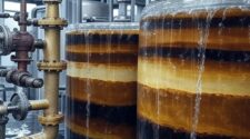
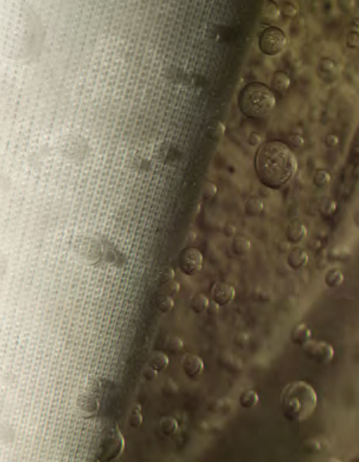
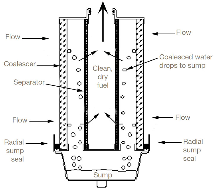
Next comes the coalescing phase, where the goal is to create a torturous path that helps pull the droplets out of another liquid and collects them. Unlike particulate filtration, where the goal is to try and block physical solids, with a coalescer, the torturous path we’ve created allows the water droplets to combine and fall out of the fluid efficiently through gravity. The larger the drops, the faster they will fall. During the third and final stage of the process, the separation phase, we are aiming to assure the separation of the water from the rest of the liquid. The separator essentially acts as a screen to repel any water droplets that may be lingering around the process stream before they make their way to the outlet. The only way to ensure that this final barrier removes the water is to run it through the coalescing process before reaching the separation phase. Separators and coalescers are often discussed together as they are typically found located in the same housing.
Where Are Coalescers Used?
We’re seeing more and more need for coalescing technology in industries that utilize fuel and oil. Specifically, there is a continuous need for coalescing technology in the petrochemicals, oil and gas production, chemical, water treatment/wastewater management and power generation industries. Not only does the coalescing process remove water from other liquids, but it also re-purifies it. Whether we’re discussing oil, gas, etc., coalescing the liquid can not only improve the quality of the primary liquid, but also effectively increase its overall performance.
Although it’s not always thought of as a target application for coalescing technology, water management is an industry where coalescing technology has a tremendous impact. Here coalescing is typically used to remove other liquid based contaminant from the water, such as oil and grease.
For coalescing to have a positive impact on any of these industries, it must be done properly. Thus, proper sizing and specifying is a critical step in the process.
Specifying
As with most decision-making scenarios, knowledge is power. Having a clear understanding of all the relevant factors is crucial for specifying a coalescer. First, when sizing/designing a coalescer for a particular process, it is important to take the operating parameters into consideration. The four biggest of these parameters include the flow rate, operating pressure, operating temperature, and knowing what liquids are involved.
The process is not as simple as it can be with particulate filtration, where oversizing is done intentionally to reduce labor costs. By oversizing the filters, operations can ensure they will spend less time replacing them as the frequency to change out the prefiltration particulate filters will extend. By oversizing change out frequency could be reduced from four times a year to two. However, if that same “oversize” principle is applied with coalescing, the results will be much different. The coalescer will be oversized to the point where it’s not effectively coalescing out what it needs to.
The nature in which the liquid flows through the housing impacts the fibers and media for the filters and how the liquid exits. There won’t be enough restriction to get the droplets to coalesce before they drop out of the stream. Thus, if the coalescer is oversized, it is not going to be as efficient in removing the water from the stream.
Through coalescing, as stated above, the goal is to combine the water droplets into large drops so they can be carried to the outside surface of the cartridge. Thus, flow rate is essential. If the flow rate is too low, it may not allow the liquid to separate without creating too high of a velocity in the vessel itself and still pass through. Conversely, if the coalescer is oversized, the velocity is too low and doesn’t end up coalescing.
Generally, we are looking to size the coalescer for optimal efficiency, looking to be within +/- 15% of the design operating parameters of the system: flowrate, temperature, and pressure. Concerning sizing the coalescing filters, the general principle is based off Stokes law. If you are in need of help sizing we recommend you reach out to a filtration expert or learn more about Stokes law and how to best apply it.
Remembering to Purge
Within the vessel housing, containing both coalescer and separator, there is one operational element of the process where we often see mistakes made, the water purge. Water must be rained/collected/purged on a regular basis from a coalescing system. To further illustrate, let’s take a given vessel where the liquid is running inside out (coalescer) and outside in (separator) in the same housing. Let us say the primary liquid (whatever that may be) in the tank accounts for the majority of the volume of the tank. As you continue to run the process, the water being separated is going to settle to the bottom of the vessel as intended.
Over time, this water is inevitably going to take up more and more of that space. Both the performance of the separator filter as well as the coalescer can be impacted if the volume of this standing water reaches a certain level. To avoid this issue, this water level must be monitored and purged from the system at regular intervals.
Coalescing is a critical element of many effective industrial filtration approaches. Thus, there is tremendous incentive to ensure the process is optimized. The only way to do this is through a comprehensive understanding of the entire operation. What is being fed into the system and what is the flow rate, operating pressure and temperature? What are the known contaminants that must be filtered upstream to ensure longer life of the coalescing/separating elements, allowing them to operate at the level they need to. By understanding all of the elements in the system, a coalescer can be properly implemented.


