![Figure 1: Heat Exchanger Proventics GMBH.[22]](https://www.filtnews.com/wp-content/uploads/IFN_2_2024_crimpedmicrofiberyarns_Fig.-1-Heat-exchanger.jpg)
Energy and resource efficiency are crucial in the context of the energy transition. The building sector in particular is a major contributor to climate-damaging greenhouse gas emissions.[16] In order to reduce these emissions, a significant increase in energy efficiency in residential buildings is highly relevant.[24]
Ventilation systems with heat recovery have a big impact on reducing energy consumption of residential buildings.[24; 4; 5] Although controlled ventilation systems offer obvious benefits, such as high air quality and energy efficiency, there is still a lot of hesitation to install this systems in residential buildings.[4]
This is mainly caused due to the investment costs, space requirements, and noise emissions. However, promoting the increased use of these systems in residential buildings could make a decisive contribution to achieving the goals of the energy transition.
Product Innovation
The HaLo-Filter (High-absorption Low-pressure-loss – Filter) research project is intended to increase the acceptance of energy-efficient residential ventilation systems. Essentially, ventilation systems consist of three main components, the fans, a heat exchanger and the air filters. The aim of the research project is to combine the latter two components into a new product, the filter heat exchanger. The basis is an air-to-air heat exchanger developed by ProVentecs GmbH with the ability to transfer liquid condensate from the used to the fresh air (Figure 1).
The geometry of conventional heat exchangers, has to be adapted that liquids can be evacuated from the heat exchanger. With the heat exchanger developed by ProVentecs GmbH this adjustment is not necessary, which means that the geometrical dimensions can be significantly reduced while maintaining the same degree of heat transfer. However, to ensure a hygienic air transport, the heat exchanger has to be replaced at regular intervals.
Another of the three main components of a ventilation system has to be exchanged to a similar interval: the air filters. The combination of these two replacement components is intended to compensate for the disadvantage of replacing two components. This also leads to a significant reduction of space required for heat exchanger and air filters, allowing smaller, more inconspicuous ventilation units.
Requirements Air Filter
The requirements a fiber filter media has to meet to be integrated in a heat exchanger are contradictory. At first the pressure drop of the filter media has to be minimal to prevent excessive high increase in power consumption and noise emission of the ventilation system.[14; 6] On the other hand, the filter efficiency of the filter media has to meet the classification as a fine filter media.[6; 30] Conventional filter media reduce the pressure drop by increasing the filter surface based on the geometry used. Due to the integration of the filter media into the flow channels of the heat exchanger, it is not possible to increase the filter surface. The shape of the filter media has to be adapted to the geometry of the heat exchanger.
The requirements for the filter media are therefore not only determined by the filtration properties, but also by the geometrical dimensions of the heat exchanger and the available free flow cross-sections. The filtration properties of a fiber filter are mainly defined by two parameters, the fiber diameters and the porosity of the material, i.e. the ratio of solid to void fractions of the fiber filter. Fiber filter theories can be used to analyze the influence of fiber diameter, porosity, and flow velocity on filtration properties and pressure drop.[17; 8; 29; 19] All theories for fiber filter media are based on the basic separation mechanisms of aerosol particles from a gas on individual fibers (Figure 2).
![Figure 2: Particle separation by interception, inertial impact and brownian diffusion.[22]](https://www.filtnews.com/wp-content/uploads/IFN_2_2024_crimpedmicrofiberyarns_Fig.-2-Particle-Separation.jpg)
The development of an analytical calculation program enables the determination of the required filter parameters. For classification as fine filter media, a minimum efficiency of 35% is required in relation to particles with an equivalent diameter of 0.4 μm.[12] The maximum pressure drop of the filter media generated should be in a range significantly below 50 Pa in order to keep the necessary energy and thus the power consumption of the ventilation system at a minimum value. The calculations show that a fiber filter media with fiber diameters of 0.9 μm at a porosity of 99.98% have to be achieved to meet the requirements of maximum pressure drop and minimum filter efficiency (Figure 3). In general, a fiber air filter that is energetically and separation efficient should be composed of fibers that are as fine as possible with low fiber compaction.[7]
![Figure 3: Calculation program for filter efficiency and pressure drop.[22]](https://www.filtnews.com/wp-content/uploads/IFN_2_2024_crimpedmicrofiberyarns_Fig.jpg)
Process Development
The state-of-the-art in fiber filter media production are the nonwoven technologies such as meltblown, spunbond or staple fiber nonwovens.[17; 2; 20] In particular, the meltblown process enables the economical and process-reliable production of ultrafine fiber nonwovens with fiber diameters in the lower micrometer and upper nanometer range.[2; 20; 13]
Meltblown is a single-stage process in which a thermoplastic polymer granulate is melted in an extruder and fed directly into the spinnerets. The viscous polymer exits through fine capillaries, solidifies into fine fibers that are stretched and entangled by the turbulence in the free jet, and is deposited to form a nonwoven fabric. Besides the fiber diameters, the grammage of the nonwoven is the second decisive production-related parameter. It is an indicator of the porosity of the fiber media and thus also of the filter media. Conventional meltblown nonwovens typically range in grammages from 3 to 100 g/m².[2; 13] In order to integrate a nonwoven into the flow channels of the heat exchanger a grammage of < 0.1 g/m² has to be achieved for the required porosity.[2]
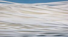
With the state of the art it is currently not possible to produce a nonwoven with the necessary filtration properties, which means that an alternative manufacturing process is required. Decoupling of the single-stage meltblown process is the basic idea of the manufacturing process for the HaLo filter media. In this approach, an endless microfiber multifilament yarn is first produced. The straight microfiber multifilament yarn has to be further processed to produce a voluminous semi-finished textile product that achieves a filtration effect. Applied and attached to the heat exchanger plates a deep air filter media with increased dust holding capacity and a low pressure drop gradient, flowing longitudinally to the filter surface, is created (Figure 4).
![Figure 4: Manufacturing process halo filter.[22]](https://www.filtnews.com/wp-content/uploads/IFN_2_2024_crimpedmicrofiberyarns_Fig4.jpg)
Fiber Innovation
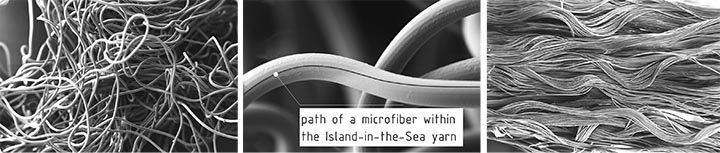
To produce an endless multifilament yarn with fiber diameters in the lower micrometer range, the Island-in-the-Sea melt spinning process is preferred.[26] With this process a bicomponent yarn is spun in which the individual microfibers are embedded in a lost matrix. A polymer combination of polyamide 12 (PA12) for the microfibers and a water-soluble polyvinyl alcohol (PVA) matrix component is used to produce the Island-in-the-Sea multifilament yarn for HaLo-Filter production.
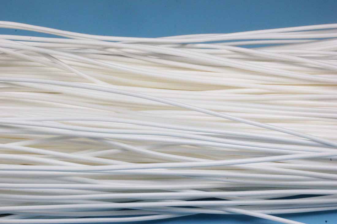
Currently, no commercial Island-in-the-Sea multifilament yarn with the required microfiber diameters of < 1.0 µm and a water-soluble matrix component is available.[23; 31] Therefore, the development of the microfiber yarn was implemented within the research project. To date an Island-in-the-Sea multifilament yarn with microfibers of approx. 900 nm and a technical and textile strength of 61 cN/tex can be produced. Due to the mechanical and polymer properties the yarn can further be processed in technical and texturing processes (Figure 5).
![Figure 5: Island-in-the-sea microfiber multifilament yarn. [22]](https://www.filtnews.com/wp-content/uploads/IFN_2_2024_crimpedmicrofiberyarns_Fig5.jpg)
Microfiber Crimping
The textile industry uses the process of texturing to increase the overall volume and elastic elongation of synthetic fibers. This results in a three-dimensional, crimped yarn structure that achieves a filtration effect comparable to nonwovens fabrics.[21; 15; 25] To create a permanent fiber crimp, two main texturing processes are used.[21]
During the Bulked-Continuous-Filament (BCF) process, a multifilament yarn is forced in an expansion chamber by a hot gas stream to form a three-dimensionally crimped yarn plug. By subsequently cooling the applied structure, which is a compose of semicircular arcs, is permanently fixed.[21; 18] The second main texturing method is the false twist texturing process (DTY). Within this process a multifilament yarn is twisted by a twist applicator, this structure is fixed by heating and cooling and then the yarn is twisted back again. A three-dimensionally crimp is applied to the multifilament yarn which leads to screw or helical turns.[21; 1]
- BCF PROCESS: Texturing of fibers with a minimum of 1.5 dpf; Corresponds to a fiber diameter of about 13 μm for PA12 fibers.[21]
- DTY TEXTURING: achieves titer per filament of just under 0.2 dpf; Corresponds to a fiber diameter of at least 4 – 5 μm for PA12 fibers.[1]
The microfiber yarn developed within the research project achieves a titer per filament of 0.007 dpf and is thus significantly below the currently minimum possible fiber titer. Using the entire Island-in-the-Sea yarn, including the lost matrix, during texturing allows the fiber diameter to be adapted to both the BCF and DTY process. In addition, microfiber breaks are avoided which ensures a reliable production.
The Crimp contraction (Chart 1), can be determined by the ratio of crimped and stretched length using standardized methods.[11] This parameter provides information about the increase in volume of the yarn due to texturing. This allows the evaluation of the two processes by the porosity applied to the filter media.
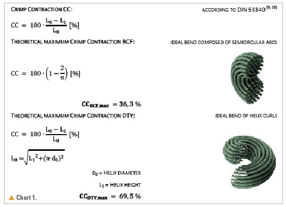
The maximum possible values of crimp contraction can theoretical be determined based on trigonometric relationships of the ideal crimp structures.[18; 21]
In order to determine and evaluate the crimp contractions of the two texturing processes according to the standard, various series of tests were carried out (Figure 6).
![Figure 6: Measurement of crimp contraction according to standard.[22]](https://www.filtnews.com/wp-content/uploads/IFN_2_2024_crimpedmicrofiberyarns_Fig.-8-Crimp-Contraction-copy.jpg)
The BCF method results in significantly higher crimp contraction in all measurement series. The theoretically determined values and the assumption that DTY texturing achieves higher values in crimp cannot be confirmed by the measurements according to the standardized method. Further measurements as well as optical analyses of the textured yarns suggest that the DIN standard results provide an inaccurate account of the texturing results.
By measuring the entire force-elongation curve of a crimped yarn the uncrimping work can be determine. This is the required energy to strecht the yarn to the point of complete decrimption.[18; 27] This allows a verfication of the DIN measurement results. Based on the uncrimping work, both the theoretical curvature and the crimp geometry of the textured yarn can be determined. This provides information about the number of arcs per length as well as the dimensions of the arcs such as arc radius, arc length or arc height.[18; 3] (at right).
Besides the uncrimping work this methode provides the determination of the total crimp contraction contained in the yarn (Figure 7).[18; 27] Particularly in case of fibers under 0.1 dpf, the crimp contraction value is determined insufficiently due to the measuring principle according to the DIN standard.
![Figure 7: Crimp contraction and crimp geometry – fiber tensile testing method.[22]](https://www.filtnews.com/wp-content/uploads/IFN_2_2024_crimpedmicrofiberyarns_fig7-811x1024.jpg)
The evaluation of the theoretical curvature clarifies the different crimp structures of the texturing methods. Within BCF, many but plane bends are produced. This structure only leads to a very small increase in volume in the yarn, which means that the required high porosity in the filter material cannot be achieved. The DTY process produces structure of arcs with a high angle of curvature but a small arc number. The overarched curvatures achieved by the high crimping angles enable a high volume increase in the yarn and thus increased porosity in the filter media (Figure 7).
An ideal crimp for the use of the crimped yarn as a highly porous filter media would consist of a high number of arcs with high crimp angles and small arc dimensions. The crimp contraction alone does not allow a reliable statement about the suitability as a filter media, it is an indicator, but the crimp geometry has also to be determined. To create a high filter porosity high crimp angles are necessary and this can only be achieved be the DTY process. The process principle of BCF prevents this.
The crimp geometry applied by BCF is limited to the dimensions of the yarn itself. The theoretical considerations already clarified that the crimp angle by BCF can reach a maximum value of π assuming an ideal compose of semicircular arcs.[18; 3] If this is the case, the diameters of the fiber are in contact. Further compression of the fibers is not possible and the arc dimensions are defined by the dimensions of the fiber. The use of the Island-in-the-Sea yarn during the texturing process results in the limitation of the maximum curvature of the microfibers embedded in the PVA matrix to the dimension of the Island-in-the-Sea fibers. After removing the water soluble PVA Matrix the curvature applied leads only to a slight undulation of the microfibers due to the significantly small microfiber diameters. As a result, the high porosity required for the purpose of filtration cannot be achieved (Figure 8).
This limitation of the maximum angle of curvature is avoided by the crimping structure as helix curls of DTY, higher and overarched crimp angles can be achieved.
Filter Production
The final step to produce the HaLo-filter media involves the processing of the textured Island-in-the-Sea multifilament yarn. First, the water-soluble PVA matrix has to be removed from the microfibers. Subsequently, the crimping of the microfibers is reactivated under the influence of heat. Applying temperature to the yarn causes shrinkage in the textured microfibers, maximizing the bulk and volume of the crimped microfiber yarn.[11; 3; 28]
Due to insufficient fiber crimp of the microfiber yarn, the goal of producing the highly porous HaLo-filter media could not yet be achieved. The goal after completion of this research project (in December 2023), is to submit a follow-up project in order to be able to optimize the microfiber crimp and to investigate the remaining open questions in more detail.
References:
- [ATK 12] Atkinson, Colin; False Twist Textured Yarns; Elsevier; Woodhead Publishing Lim-ited; 2012.
- [BAT 15] Batt, Till; Entwicklung eines Meltblow-Verfahrens zur Herstellung thermoplas-tischer Feinstfaser-Vliesstoffe; Universität Stuttgart; 2015.
- [BAU 00] Bauer-Kurz, Ina; Fiber crimp and crimp stability in nonwoven fabric processes; Dissertation; North Carolina State University; 2000.
- [BUN 22] Bundesverband der Deutschen Heizungsindustrie e. V. (BDH); Fachverband Gebäude-Klima e.V. (FGK); Beitrag der Wohnraumlüftung mit Wärmerückgewin-nung zur Reduktion fossiler Energien und Reduktion der CO2-Emissionen im Gebäudesektor 2022.
- [BUN 22] Bundesverband der Deutschen Heizungsindustrie e. V. (BDH); Fachverband Gebäude-Klima e.V. (FGK); Stiefkind Wohnungslüftung mit Wärmerückgewin-nung? 2022.
- [CEA 13] Ceasar, Thomas; Industrielle Luftfiltration; Moderne Industrie; 2013.
- [DAU 12] Dauner, Martin; Batt, Till; Abschlussbericht NaBlo: Nano-Meltblown-Fasern für Filtermedien 2012.
- [DAV 73] Davies, Charles Norman; Air Filtration; Academic Press; 1973.
- [DIN 83] DIN 53840 – 1; Bestimmung von Kräuselkennwerten an texturierten Filamentgar-nen.
- [DIN 83] DIN 53840 – 2; Bestimmung von Kräuselkennwerten an texturierten Filamentgar-nen.
- [DIN 06] DIN EN 14621; Prüfverfahren für texturierte und nicht texturierte Multifilament-garne.
- [DIN 12] DIN EN 779; Partikel-Luftfilter für die allgemeine Raumlufttechnik.
- [DRA 19] Drabek, Jiri; Zatloukal, Martin; Meltblown technology for production of polymeric microfibers/nanofibers: A review 2019.
- [FAI 99] Faist Wolfgang Dr.; Anforderungen an die Wohnungslüftung im Passivhaus 1999.
- [FAL 81] Falkai, Béla von; Bonart, Richard; Synthesefasern; Verl. Chemie; 1981.
- [PHI 20] Fraunhofer-Institut für Solare Energiesysteme ISE; Studie: Wege zu einem klima-neutralen Energiesystem 2020.
- [GAI 18] Gail, Lothar; Gommel, Udo; Reinraumtechnik; Springer Berlin Heidelberg; 2018.
- [GEI 69] Geitel, Karlheinz; Die Bogenzahl, eine notwendige Größe zur Beschriebung der Kräuselung? 1969.
- [GOU 96] Gougeon, R.; Boulaud, D.; Renoux, A.; Comparison of Data from Model Fiber Filters with Diffusion, Interception and Inertial Deposition Models 1996.
- [GRI 19] Gries, Thomas; Veit, Dieter; Wulfhorst, Burkhard; Textile Fertigungsverfahren;3., überarbeitete und erweiterte Auflage; Hanser; 2019.
- [HEA 01] Hearle, J. W. S.; Hollick, L.; Wilson, D. K.; Yarn texturing technology; CRC Press/Woodhead Publ; 2001.
- [HER 23] Herrmann, Lukas; Abbildungen ProVentecs GmbH. https://www.proventecs.de/. 27.10.2023.
- [HIL 23] Hills Inc.; Fibers. http://www.hillsinc.net/fibers/. 27.10.2023.
- [JUG 21] Jugel, Christoph; Abschlussbericht dena-Leitstudie Aufbruch Klimaneutralität 2021.
- [KOS 97] Koslowski, Hans J.; Chemiefaser-Lexikon;11. Aufl.; Dt. Fachverl.; 1997.
- [MUK 14] Mukhopadhyay, S.; Bi-component and bi-constituent spinning of synthetic poly-mer fibres; Woodhead Publishing Limited; 2014.
- [REU 00] Reumann, Ralf-Dieter; Prüfverfahren in der Textil- und Bekleidungstechnik; Sprin-ger-Verlag Berlin Heidelberg GmbH; 2000.
- [STR 16] Straovoytova, Diana; Analysis of Effect of Heat-Setting Temperatures on Crimp Parameters in Polypropylene Single-Fibres 2016.
- [THO 17] Thomas, Dominique; Charvet, Augustin; Bardin-Monnier, Nathalie; Appert-Collin, Jean-Christophe; Aerosol Filtration; ISTE Press; Elsevier; 2017.
- [VDI 18] VDI 6022; Raumlufttechnik, Raumluftqualität.
- [WIL 23] Wilkie, A.; Multi-component Fiber Technology for Medical and other Filtration Applications. http://www.hillsinc.net/assets/pdfs/multi-component-fiber-medical.pdf. 27.10.2023.


